Isometric symbol editor
You can create and edit isometric drawing symbols with a special symbol editor. The symbols are drawn in a square of 100 x 100 units.
Starting to create a new isometric drawing symbol or double-clicking an existing one opens the Edit Symbol dialog.
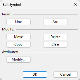
Insert
Use these commands to draw lines and arcs in the symbol. When picking a point, you can use the navigation commands listed in the context menu, as well as snap to existing vertex points.
-
Line – Select this to draw lines by first picking the start point and then one or more additional points along the required path.
-
Arc – Select this to draw arcs by first picking the center point and then the start and end point.
Modify
Use these commands to manage the drawing objects of the symbol.
-
Move – Select this to move existing drawing objects.
-
Copy – Select this to create copies of a set of selected drawing objects.
-
Delete –Select this to delete a set of drawing objects.
-
Clear – Select this to delete all drawing objects.
-
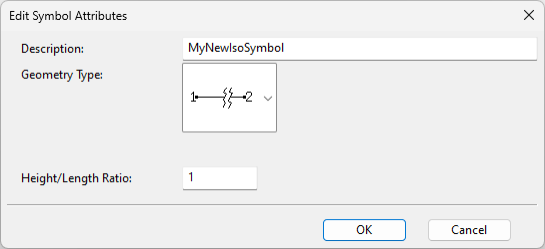
Modify – Opens the Edit Symbol Attributes dialog where you can specify the following.
-
Description – Enter a name for the isometric drawing symbol.
-
Geometry Type – The geometry type must be the same as what is specified in the dimension table. The linking point of the symbol appears in the drawing area based on the geometry type.
-
Height/Length Ratio – The size of the symbol depends on the setting Symbols > Length of symbol [mm]. By default, this value is 20 mm, which means both the height and the length of the symbol are 20 mm.
-
For geometry types DM_GT_2P, DM_GT_VALVE, and DM_GT_PENETR, the length also depends on the height/length ratio. For example, if 'Length of symbol' is 20 mm and the ratio is 2.0, the length becomes 10 mm. This is used, for example, to create shorter symbols for gaskets, flanges, penetration flanges, and orifice plates.
-
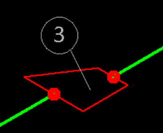
For geometry type DM_3PDIRFIX, the height also depends on the height/length ratio. For example, if 'Length of symbol' is 20 mm and the ratio is 2.0, the height becomes 10 mm. This is used, for example, to create neat symbols for eccentric reducers (see the image below, where an H/L Ratio of 3.0 is used).
-
For other geometry types, the width equals the height.
-
-